Working with unfamiliar hardware can be both frustrating and exhilarating. This post is about how I tinkered my way through flashing the TB-03F chip — a super-cheap, low-power SoC, to create a functional clone of Apple’s AirTag, using entirely open-source tools that are usable on any platform.
The Spark: Discovering the TB-03F
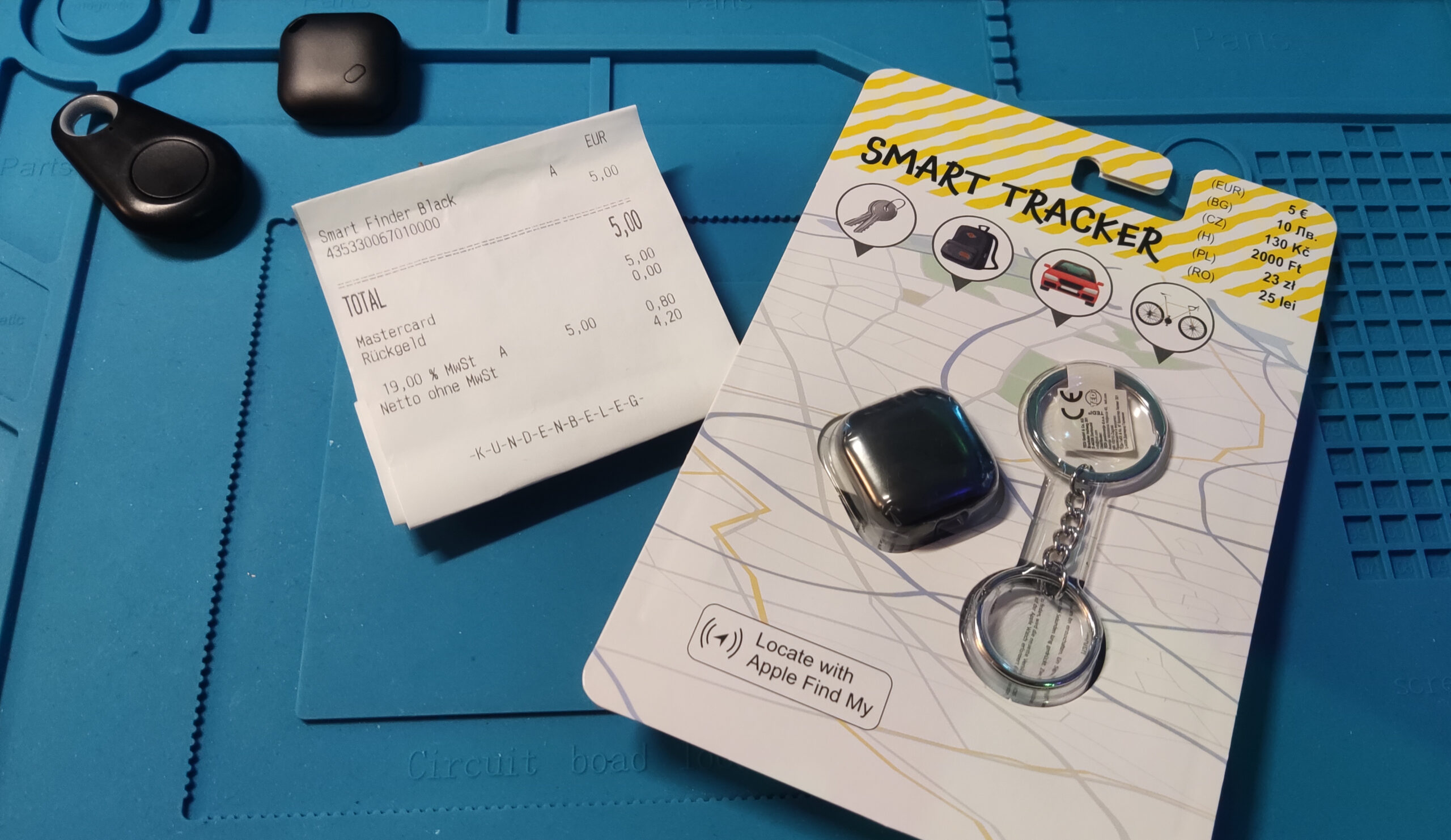
It all began when I discovered OpenHaystack, an open-source project that enables tracking devices using Apple’s Find My network. I quickly came across Aaron Christophel’s YouTube video showcasing how to build a €2 AirTag clone using the TB-03F module.
While the idea was solid, I found the firmware very limiting — it was closed source, lacked rotating keys, had no battery reporting, and could only be flashed via a Chrome based browser tool. That wouldn’t do. The hardware, though, had potential.
Getting the Hardware
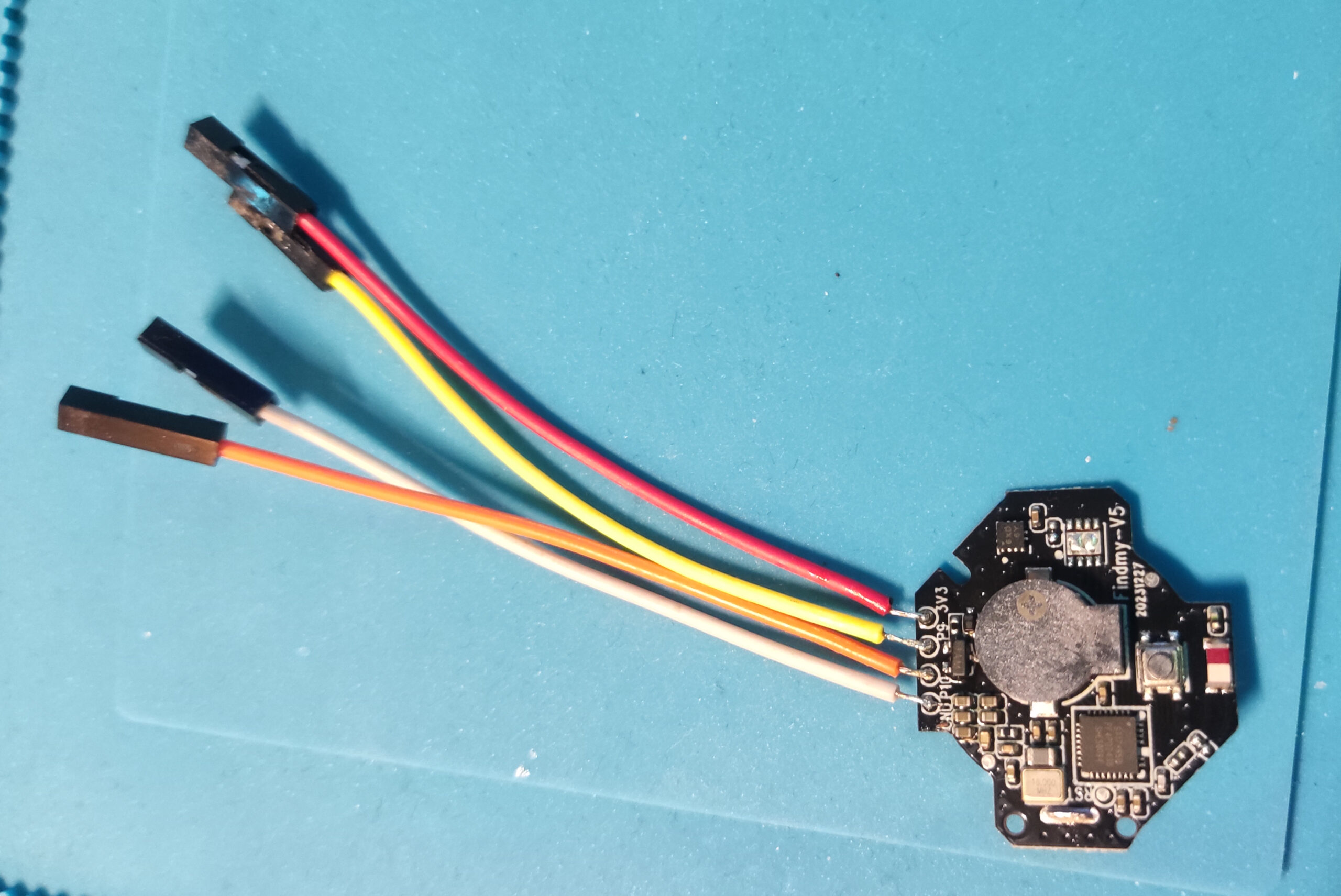
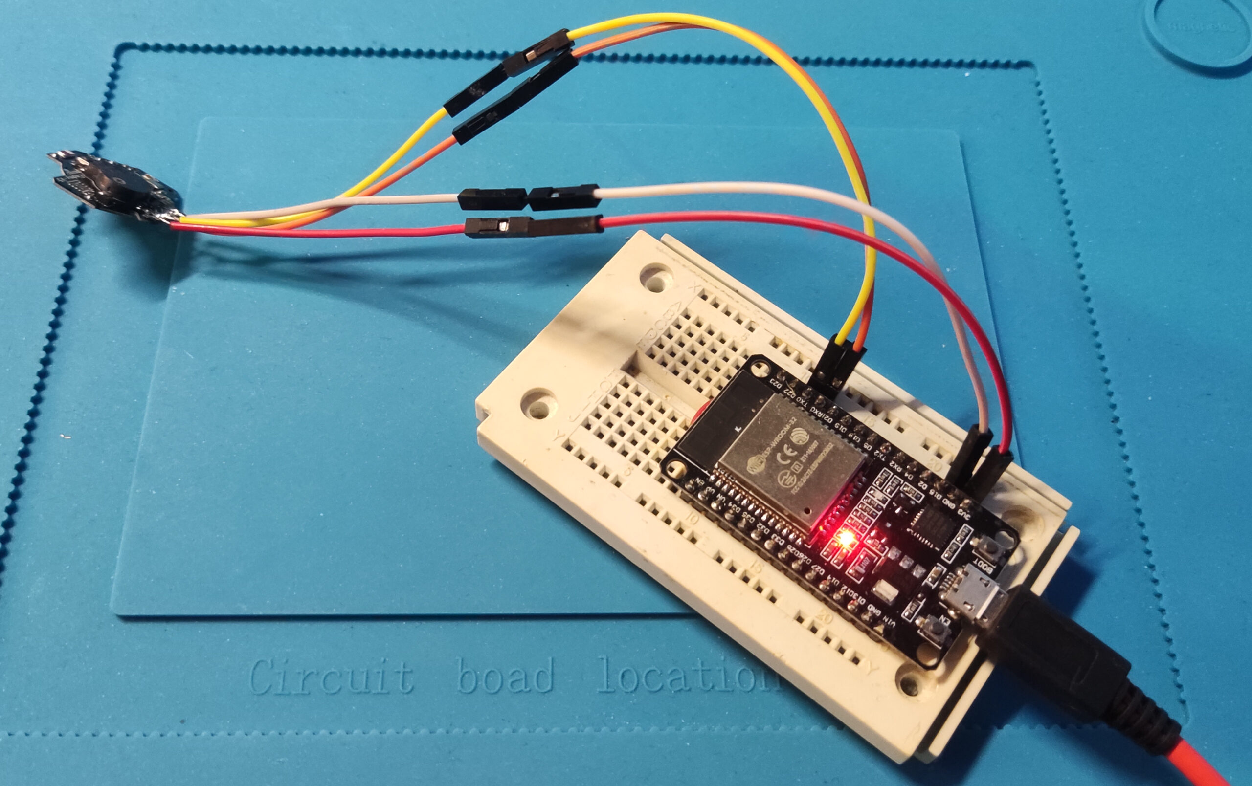
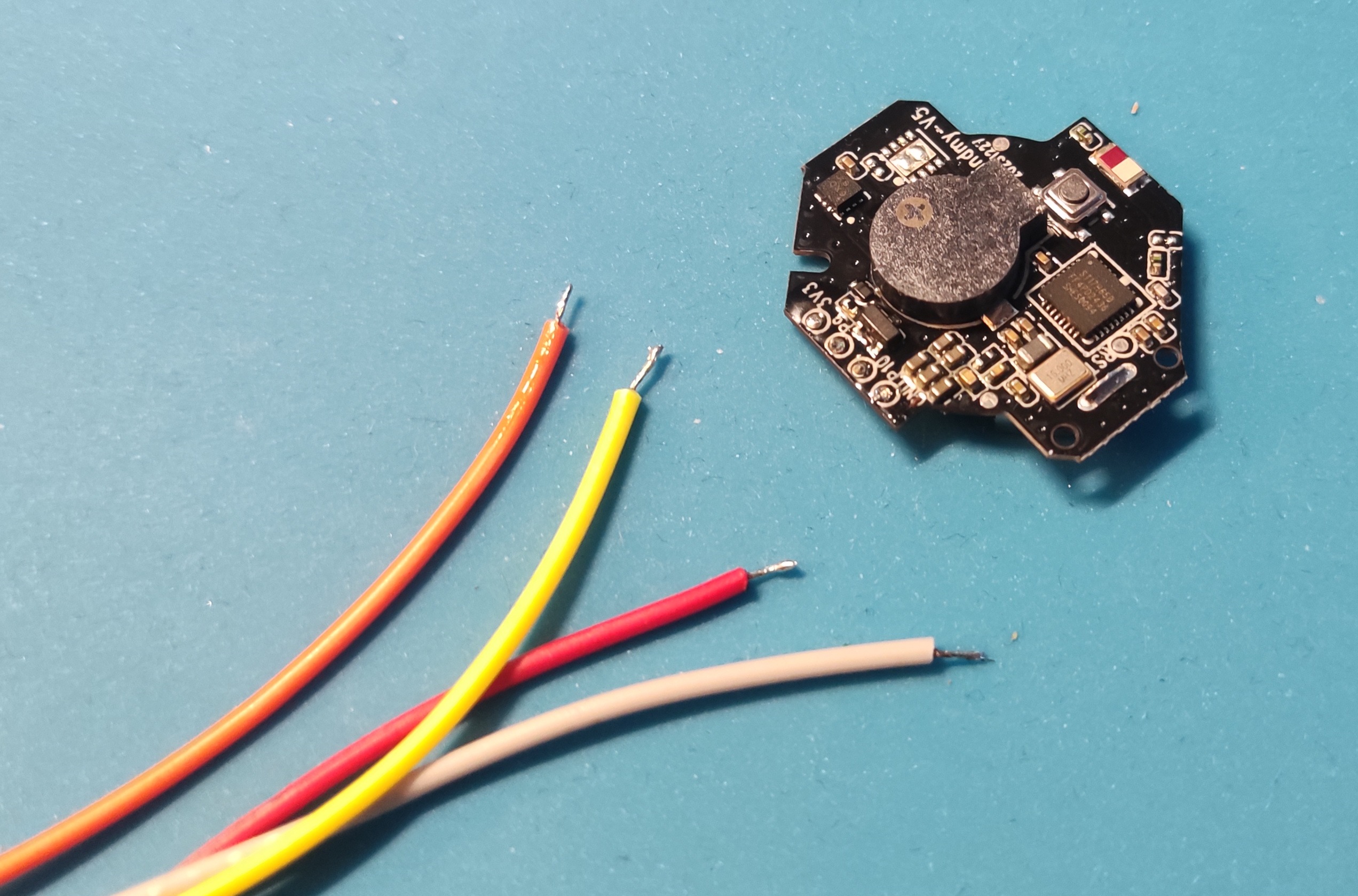
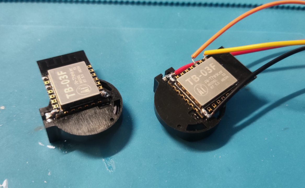
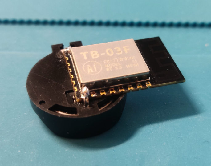
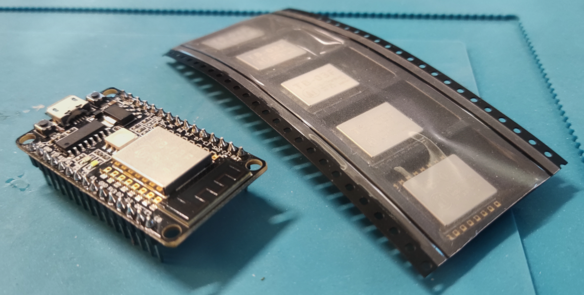
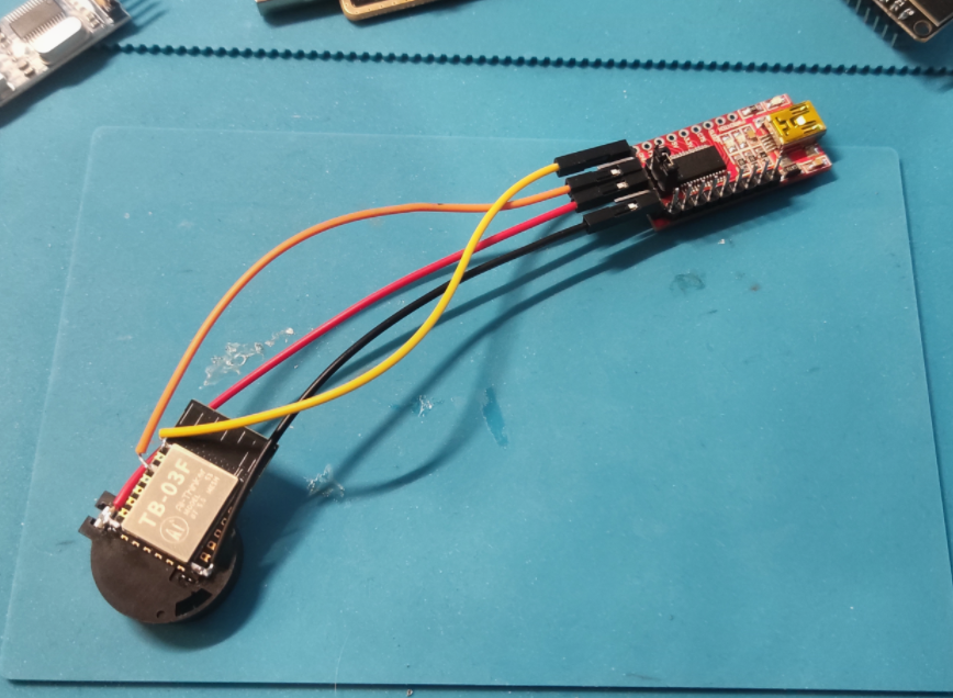
I ordered some TB03F modules and, a bit later, a NodeMCU-style TB03F development board for easier debugging.
While waiting for the dev board, I got started with what I had.
The First Hurdle: Flashing
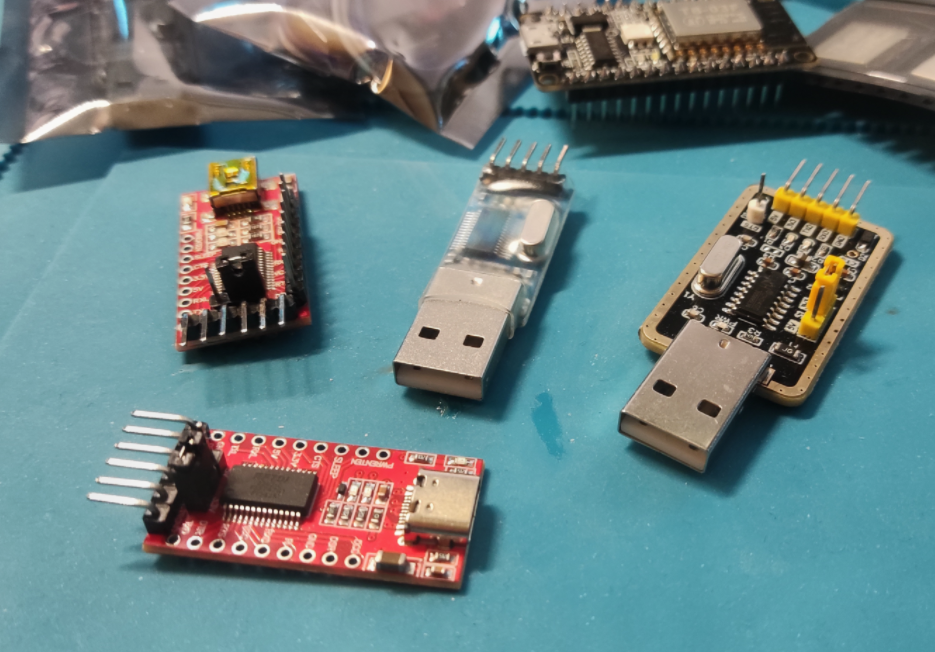
Flashing these chips is not as straightforward as with something like an ESP8266. Initially, I tried using various USB-to-TTL adapters – FTDI, CH340, CP2102 – you name it. I even ordered a variety pack of cheap adapters. Turns out, the USB-C ones are ALL garbage – no exceptions.
In the end, none of the adapters I tried worked with the
flashing method provided by the SDK.
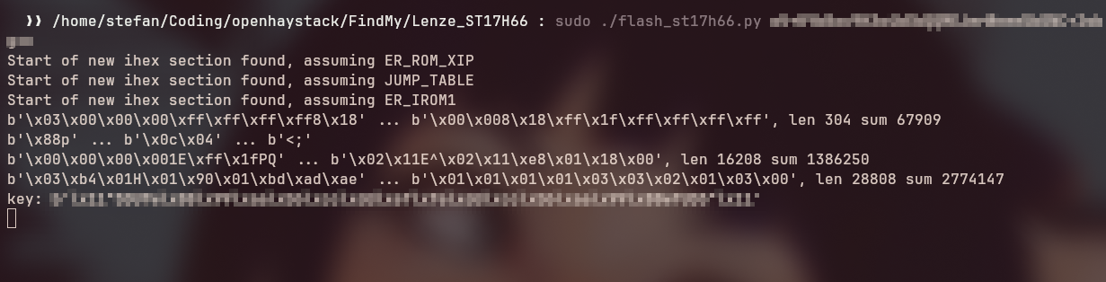
Eventually, I pulled the JavaScript flasher code from Christophel’s site and ported it to Python using pyserial. That way, I had full control over the flashing process and could run it offline.
How the Flasher Works (Quick Deep Dive)
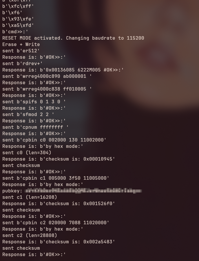
The Telink chip doesn’t use standard serial upload protocols like esptool or dfu-util. Instead, it requires bit-banged commands over UART to simulate Single-Wire Serial (SWS) communication. Here’s a simplified breakdown:
- Reset the MCU using DTR/RTS pins.
- Send SWS commands to write to internal registers.
- Unlock the flash memory for writing.
- Erase sectors and write 256-byte blocks.
- Soft reset the chip after flashing.
The flasher does all this using custom logic to generate precise byte sequences. One critical part is the sws_wr_addr function, which translates a command or data payload into the exact 10-byte-per-byte waveform the TB03F expects.
Details on SWS
SWS is Telink’s ultra-minimal debug protocol. It transmits each bit as a full byte – essentially a bit-banged waveform – allowing even simple UART peripherals to communicate with the chip if you control DTR/RTS.
Writing Better Firmware: Key Rotation and Battery Status
The original firmware worked but lacked two major features:
- Rotating keys, which periodically changes the BLE address/advertisement data for privacy.
- Battery level reporting, to display a green/yellow/red battery indicator icon in the OpenHaystack Web UI.
I started implementing key rotation but found that the rotation only happened once – then never again. It turns out, the index counter needs to be stored in retention RAM, which persists across deep sleep cycles. Once I fixed that, rotation worked perfectly using a soft timer.

Debugging With the Dev Board
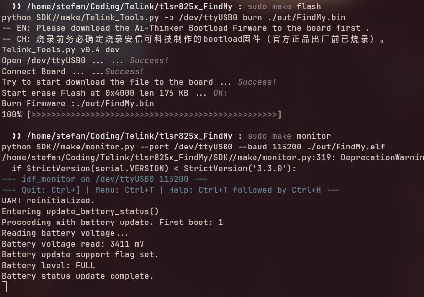
Once the dev board finally arrived, I plugged it straight into my PC and stole a basic at_print debug function which I pulled from one of the Telink SDK examples.

After adding the line
DOWNLOAD_PORT := /dev/ttyUSB0
to the Makefile, I was able to use
make flash
to upload firmware directly to the development board, and
make monitor
to view console output. This streamlined the workflow significantly and made testing changes much more efficient.
Even more important: This gave me real-time feedback from the battery voltage reading. Invaluable info while tinkering with the battery advertisement feature
Reading Battery Voltage Without Extra Wires
One goal was to minimize physical modifications to the modules – ideally, I wanted to track battery life without needing a separate ADC wire.
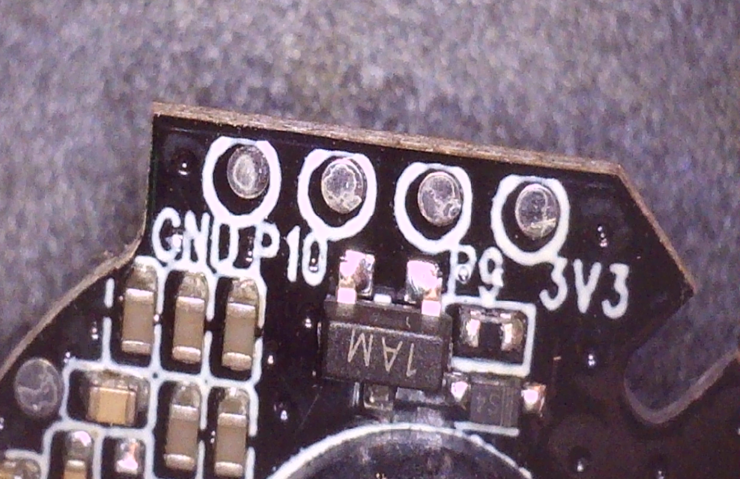
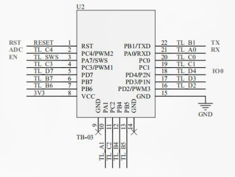
After digging into slow-loading chinese docs and repos, I discovered that PB7 can be used as a pseudo-ADC:
- Set PB7 high.
- Immediately read its voltage — this reflects VBAT.
This works because PB7 is internally connected in such a way that its GPIO HIGH voltage mirrors the battery level. So, I could get a working readout with only VCC and GND connected – no extra wires or soldering! Of course, the actual implementation is a little more tricky – and stolen from the SDK as well. 🙂

Broadcasting the Battery Level
Next, I figured out how to add the voltage reading to the BLE advertising packet. Apple reserves the 7th hex byte in its implementation for battery level. I looked into how Biemster did this for nRF52-based devices and mimicked it:
- Measure voltage at boot and every 14 days.
- Write it to retention RAM.
- Inject the value into the BLE advertisement payload.
And it worked! I saw my device show up in OpenHaystack with the correct battery icon.
To set the battery level in the BLE advertisement correctly, the 7th byte (index 6) is masked and updated using predefined bit patterns. The upper two bits of that byte are reserved for battery status, so we use a bitmask to preserve the rest of the data while only modifying those two bits. Specifically, the line:
tbl_advData[6] = (tbl_advData[6] & ~STATUS_FLAG_BATTERY_MASK) | stored_battery_status;first clears the battery bits using the inverse of STATUS_FLAG_BATTERY_MASK (which is 0b11000000), and then sets them to one of the defined levels like STATUS_FLAG_LOW_BATTERY or STATUS_FLAG_FULL_BATTERY, depending on the voltage reading. This approach ensures only the relevant bits are changed without affecting other parts of the advertisement byte.
Wrapping It All Up
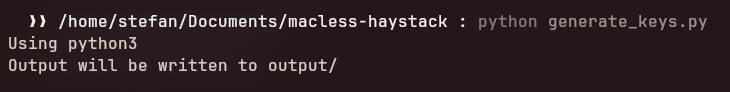
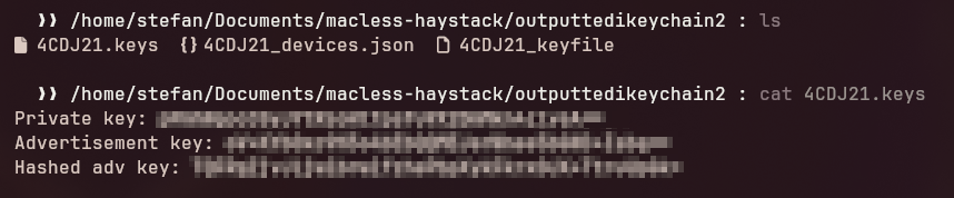
In the final version, I removed all debug logs, generated a fresh set of keys, flashed the firmware using my Python tool, and… success again!
The device started advertising immediately and showed up with a green battery symbol in the OpenHaystack app just minutes later.
The firmware and all the tools can be found in my repo:
https://github.com/stefexec/TB-03F-OpenHaystack-Firmware/
Final Thoughts
This project taught me a lot — not just about the TB-03F chip, but also about low-level firmware flashing, BLE broadcasting, and managing power on embedded systems. If you’re into microcontrollers, privacy-respecting tracking, or just want to tinker, the TB-03F is a fun chip to explore.
Sources:
https://docs.ai-thinker.com/_media/ble/docs/tb-03f_product_specification_en_v1.0.pdf
https://github.com/Ai-Thinker-Open/Telink_825X_SDK/
https://docs.ai-thinker.com/_media/tb-03f-kit_specification_en.pdf
http://wiki.telink-semi.cn/doc/an/AN_17092700-E_Telink%20826x%20BLE%20SDK%20Developer%20Handbook.pdf
https://tuprints.ulb.tu-darmstadt.de/29727/1/Alexander_Heinrich_Dissertation.pdf
https://github.com/dchristl/macless-haystack/tree/main/firmware/nrf5x